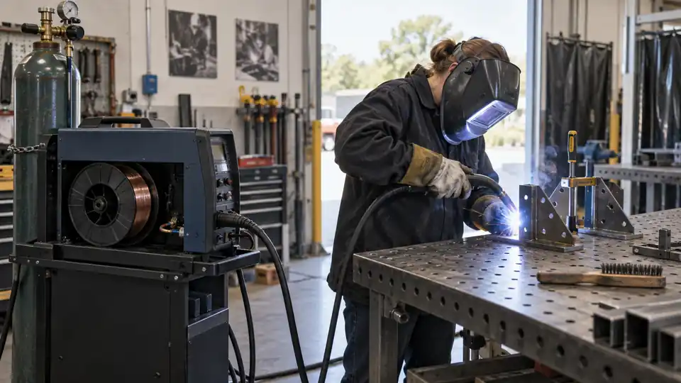
Learning how to choose a MIG welder gets much easier once the decision is tied to real work. A small machine for thin sheet and occasional repairs has different demands than a shop welder expected to run long beads on thick plate. Start with the material, thickness, available electrical supply, and welding environment, then use the machine’s specifications to confirm that fit.
A MIG welder may also support self-shielded flux-core welding, but that does not automatically make it suitable for every MIG application. Solid-wire MIG needs shielding gas, aluminum may require a spool gun or another specialized feeding setup, and a welder’s maximum amperage says little about how long it can sustain that output. Those distinctions shape the buying decision more than a flashy control panel or a large number on the front.
Start With the Work, Not the Machine
Think about the projects that will actually land on your welding table. A person repairing mower brackets, small trailers, or mild-steel tubing may value simple setup and dependable wire feeding. Someone fabricating frames from heavier sections may need more output, a longer duty cycle, and a circuit that can support the machine at its rated performance.
Write down the materials, approximate thicknesses, weld lengths, and locations before comparing models. A welder used for short tack welds in a garage faces a different workload from one making repeated structural joints while the fan hums and the torch cable stays warm. This short inventory prevents a common mistake: buying for a once-a-year project while sacrificing useful features for everyday work.
| Work requirement | What to examine | Why it matters |
|---|---|---|
| Thin sheet or light fabrication | Low-current control, stable wire feed, suitable wire sizes | Helps reduce burn-through and makes short welds easier to manage |
| Repeated welds or long seams | Rated output and duty cycle at that output | Shows how often cooling pauses may interrupt the work |
| Outdoor repairs | Flux-core capability and wind exposure | Self-shielded flux-core avoids a shielding-gas bottle, but creates different cleanup and fume conditions |
| Aluminum projects | Spool-gun or push-pull support, suitable wire and gas | Aluminum wire can feed poorly through a conventional long gun liner |
Choose the Process Configuration
Many machines marketed as MIG welders support more than one wire process. A machine may run solid wire with external shielding gas, self-shielded flux-core wire without external gas, or gas-shielded flux-core wire when the manufacturer supports that setup. These processes share a wire-feeding system, but their polarity, consumables, shielding method, cleanup, and operating behavior can differ.
Solid-wire MIG
Solid-wire MIG is a practical choice for clean indoor work on materials supported by the machine and consumables. The gas flowing from the nozzle shields the arc and molten puddle, so a breezy driveway can quickly turn a smooth hiss into porosity and erratic arc behavior. A garage or enclosed fabrication area with suitable ventilation usually gives this process a more controlled setting.
Self-shielded flux-core
Self-shielded flux-core wire carries ingredients that produce shielding as the wire burns. That makes it useful for outdoor repairs where wind could disturb external shielding gas, but the arc commonly produces more smoke, slag, and spatter than clean solid-wire MIG. After the bead cools, slag must be removed before inspecting or adding another pass.
Check the manual for the polarity required by the exact flux-core wire. Flux-core wires do not all use the same polarity, and connecting the work lead or gun incorrectly can produce a harsh arc and poor-looking welds. A machine’s “gasless” label should be read as self-shielded flux-core support, not as proof that it behaves like conventional solid-wire MIG.
Match Output to Material Thickness
Amperage is one of the most visible specifications on a welder, yet it needs context. A machine’s maximum output describes its upper operating range under specified conditions. It does not guarantee continuous operation at that level, and it does not establish a universal maximum material thickness.
Joint design, fit-up, material type, preheating, travel speed, wire diameter, shielding gas, and the number of passes all affect the result. A compact welder may handle useful repair and fabrication work, while a larger machine may be necessary for repeated welds on heavier material. Read the manufacturer’s recommended operating range and application guidance instead of matching a machine to a thickness chart alone.
Low-end control matters just as much for thin material. A machine that starts too aggressively can blow holes through sheet metal with a sharp pop and a glowing gap where the panel used to be. Look for a usable low-output range and controls that allow wire feed speed and voltage, or their equivalent, to be adjusted with enough precision for the work.
Understand Input Voltage and Available Power
A welder’s input voltage must fit the electrical supply where it will operate. A machine listed for 120-volt input may suit a home garage or mobile repair setup, while a model requiring 240-volt input may provide access to higher output depending on its design and the available circuit. Dual-voltage equipment can offer flexibility, but it does not promise the same output at both voltages.
Check the manufacturer’s input-current requirements, recommended circuit information, and plug configuration. A machine connected to a circuit that cannot supply its required power may have reduced usable output or nuisance breaker trips. Electrical installation or circuit changes should follow the manual, applicable electrical codes, and guidance from a qualified electrician.
For example, a person welding small brackets beside a workbench may appreciate a 120-volt setup that is easy to move and connect. A fabrication area with heavier plate and frequent long welds may benefit from a 240-volt machine, provided the site has the correct supply. The higher voltage itself does not magically improve every weld. The machine’s design and operating conditions still determine the available performance.
Read Duty Cycle With Its Test Conditions
Duty cycle describes how long a welder can operate within a stated test period at a specified output before it needs cooling time. The percentage only means something alongside the amperage and test basis. A duty cycle rated at one output does not apply unchanged across the machine’s entire amperage range.
This specification becomes more useful once the work rhythm is clear. Someone making a few short tacks on a garden gate may never approach the machine’s thermal limit. A person running repeated beads on a trailer frame may spend enough time pulling the trigger for cooling pauses to become part of the job, with the fan running and the thermal indicator eventually demanding a break.
Compare duty-cycle figures cautiously between different machines because their test conditions may differ. A larger percentage is helpful only when it is measured at an output relevant to your work and under a comparable basis.
Check Wire Feeding and Consumable Support
A smooth wire path is central to MIG performance. Inspect the machine’s supported wire diameters, drive-roll arrangement, liner requirements, spool size, and gun connection. The exact supported range belongs to the manufacturer’s documentation, since two machines with similar amperage ratings may accept different wire sizes or spool formats.
Wire-feed speed controls how quickly filler metal enters the arc. Voltage influences arc length and behavior on machines that provide separate voltage adjustment, while synergic or automatic modes may coordinate settings for a selected wire and material. These features can shorten setup, but they do not remove the need to verify the correct wire, polarity, gas, and material setting.
Consumable availability matters after the new-machine excitement fades. A machine that uses commonly available contact tips, liners, drive rolls, and wire sizes can be easier to maintain than one requiring unusual parts. A worn tip, dirty liner, wrong drive roll, or excessive spool tension can make the wire stutter through the gun, so replacement components should be easy to identify and source.
Plan Carefully for Aluminum and Stainless Steel
Steel capability does not automatically equal aluminum capability. Aluminum wire is softer than common steel wire and may bird-nest or buckle inside a conventional gun feed path. A spool gun places the small wire spool close to the gun, reducing the distance the soft wire must travel. Some systems use a push-pull arrangement instead.
Before choosing a machine for aluminum, verify that it supports the required wire, polarity, shielding gas, gun arrangement, and controls. Confirm whether the spool gun is included, optional, or unavailable. A product listing that says “spool-gun ready” describes compatibility, not necessarily an accessory inside the box.
Stainless steel also requires the correct wire and shielding-gas arrangement for the intended application. The machine may be capable of feeding the wire, yet the finished weld still depends on suitable consumables, surface preparation, gas selection, polarity, and technique. Treat each material as a complete setup rather than assuming a steel configuration transfers unchanged.
Compare Controls and Useful Features
Controls should make the intended work easier to set up and correct. A basic machine with separate wire-speed and voltage controls may suit a reader who wants direct adjustment. A synergic mode can provide a starting point by coordinating parameters around selected wire and material information, although the operator still needs to confirm the setup and tune it for joint position and fit-up.
Useful features may include a clear display, inductance adjustment, burnback control, spool-gun support, polarity access, thermal protection, and a gun connection that accepts commonly available consumables. The value depends on the work. A spool-gun connection is irrelevant to someone welding only mild steel indoors, while it becomes a major requirement for regular aluminum projects.
Be careful with accessory lists. A machine may support a spool gun without including one, offer flux-core capability without providing the preferred wire, or include a regulator that does not match every shielding-gas cylinder arrangement. Separate “included,” “compatible,” “optional,” and “sold separately” before comparing prices.
Account for the Welding Environment
Indoor solid-wire MIG and outdoor self-shielded flux-core address different conditions. Wind can disturb shielding gas, while poor ventilation can allow welding fumes and gases to accumulate. A garage door partly open may improve airflow, but airflow should not blow directly across a gas-shielded arc and disturb the protective envelope.
Base-metal coatings deserve attention too. Paint, oil, rust, and galvanizing can affect arc stability and generate hazardous fumes when heated. Remove contamination with suitable methods, follow the consumable and equipment instructions, and use ventilation or fume extraction appropriate to the work. Respiratory protection, where required, must be selected and used according to applicable safety guidance. It does not replace effective ventilation or source control.
Keep flammable materials away from sparks and hot metal, secure compressed-gas cylinders, and use the protective equipment specified for welding. The machine choice affects process behavior, but it cannot compensate for an unsafe work area.
A Practical Selection Sequence
- List the materials. Identify whether the work involves mild steel, stainless steel, aluminum, or another alloy.
- Estimate the thickness and joint types. Include thin sheet, tubing, lap joints, butt joints, and heavier sections rather than relying on one maximum thickness.
- Choose the likely wire process. Decide whether solid-wire MIG, self-shielded flux-core, or both fit the work environment.
- Confirm electrical compatibility. Match the machine’s input requirements to the circuit available at the work location.
- Compare usable output. Read amperage, voltage range, recommended applications, and duty cycle together.
- Verify material-specific equipment. For aluminum, check spool-gun or push-pull support, wire compatibility, gas requirements, and whether the needed accessories are included.
- Inspect the feed system. Confirm supported wire sizes, drive rolls, spool capacity, gun connection, liners, and replacement consumables.
- Review the manual before buying. The manual often reveals polarity options, circuit requirements, accessory limits, and setup details that a short product description leaves out.
The Practical Choice
The best MIG welder is the one whose process options, output range, electrical requirements, wire-feeding system, and accessories match the work you can describe clearly. A compact machine may be the smarter pick for light fabrication and occasional repairs, while a higher-output model earns its place through sustained work, material range, and duty-cycle capacity.
If you are still deciding how to choose a MIG welder, begin with the least glamorous details: what you will weld, how thick it will be, where the machine will run, and how often the torch will stay active. Those answers narrow the field quickly, leaving the display type, extra modes, and convenience features to serve the job rather than drive the purchase.
